Useful Bits
Small Diesel Coupling Boxes
By request I drew a copy of the coupling box used on Simplex locos, it is 4 slot and a 0.7mm pin goes through the hole to hold the coupling link in place. For prototypical industrial use, fiddly and no auto coupling, but they do look right.
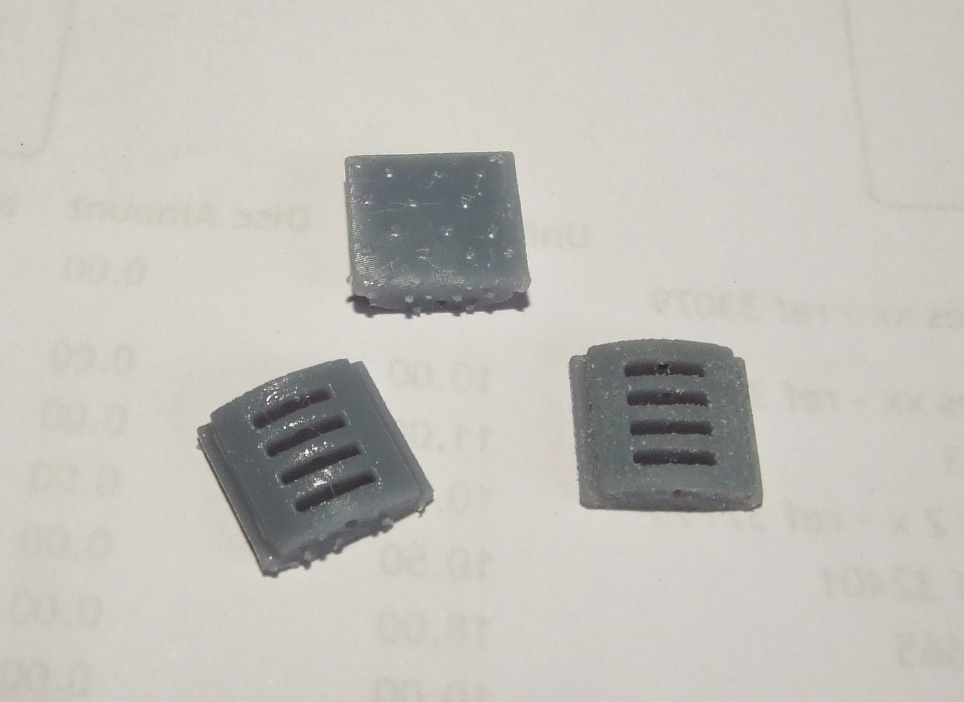
The two on the left show them straight from the printer, the one on the right has been filed flat to remove pips and the hole cleared with a drill. They measure 12mm wide, 10mm high and 3mm thick, £1.00 a pair. I can make other types if there is a need.
Dick Kerr PE axleboxes
Designed for use with the Worsley Works etches and 3D resin printed, available in 7mm scale or 1/35th.
Set of 4 for £2.00
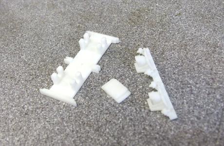
Diesel parts
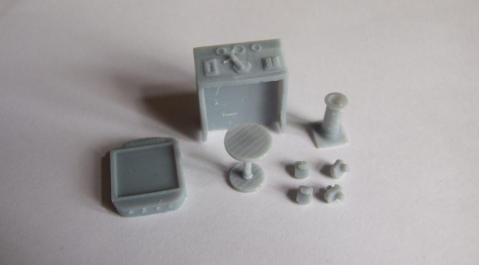
Taken from my Hudswell D29 kit, they are useful on any diesel and I have used several for detailing other diesels with no cab interior. These are straight from the printer with attachment points still showing, they can be filed or sanded flat. These are in 7mm but they can be made in any scale, I already have drawings for 16mm ones. Prices are from £5.00 a set and vary with scale, you can have individual parts if you want from £2.00.
Garratt cylinders
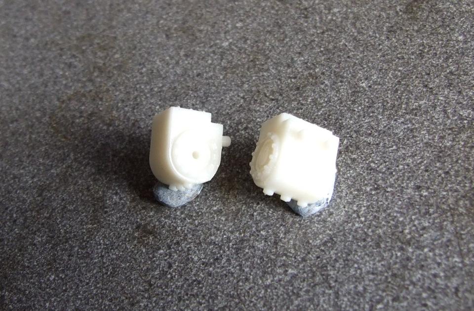
I call these Garratt cylinders as they were drawn for a Garratt I am scratch building. They suit large locos as they measure 14mm across the end covers, the cylinder part is 12mm diameter and height of the valve inspection cover is 15mm. Location is with 2 pegs on the rear, just drill holes in your frames to suit. The 3 pegs underneath are automatic drain cocks, quite common from the 1920s onward. These were designed for a chassis with outside frames, I can make an extended version for inside frames by adding 1.5mm to the mounting face.
Garratt cylinders with brass tube for piston rod £6.00 a pair
I have suitable single slidebar crossheads to fit these at £4.00 apair
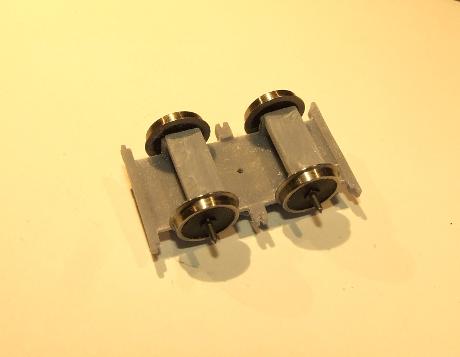
Wheel Fitting Jig
Like many others I always struggle to get wheels onto axles, plain axles are not so bad as they can be done in a vice, pinpoint axles being the worst as you have to not damage the points as well. I often take 5 minutes per axle gently tweaking the wheels to get them square and to gauge so I thought about some kind of jig to do the hard work.
A one shot jig that assembled both wheels in one go would be nice but a different one would be needed for every gauge, and I deal with 7 or 8 gauges so this is the next best thing. You get a base plate that mounts in a machine vice and a spacer for each gauge you use, the standard kit will come with 16.5, 14 and 12mm spacers. To use it you will need a vetical drill, vertical mill or an attachment that fits a lathe, and a suitable machine vice to hold the base plate. It works like this -
1 - Fit the axle in the chuck and lower towards the base plate, lining the point up with one of the drillings. 2 - Place the spacer with a wheel on top over the drilling and bring the axle back down pushing it throughthe wheel and spacer into the drilling until you feel it bottom out. 3 - remove the axle and refit the other way round and repeat step 2.
The wheels should now be fitted squarely and to gauge. Note that this only works with standard 26mm pinpoint axles and wheels of 2.5mm thickness, which mine are. For other axle lengths or wheel thicknesses different spacers will be needed which I can supply by calculating from the axle lengths, wheel thicknesses and gauge. There are 3 drillings in the base plate, this is because they will wear in time and this gives you 3 times the length of use of the jig. Also some might find it better to solder the spacers permanantly above a drilling, then you can have 3 gauges per jig.
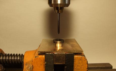
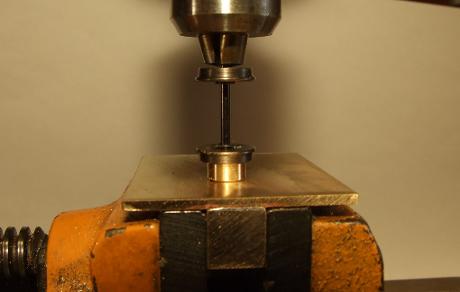
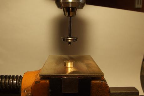
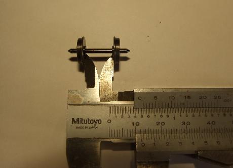
From the 4 pictures you can see the first wheel lined up and ready, after fitting it, the second wheel being fitted and the wheelset shown being checked on a vernier gauge, fortunately it was a 14mm gauge set I was hoping for. When you first try it, it might take a few minutes to do the first one, when you get the idea they can be done in less than 30 seconds each.
I can supply these for £12.00 each with extra spacers foc if ordered with the jig
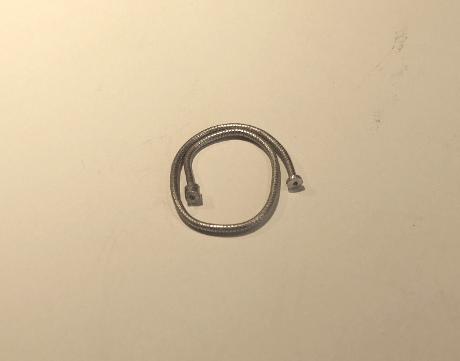
Water pick up hose
For use on WD locos, on the roof of the Joffre or hanging on the brackets of other types. 120mm long, longer lengths on request, and 2mm diameter with a can on one end and a flange on the other, the hose part is rolled to give it texture similar to a canvas hose of the period. It is made of solder so can be bent to shape but must be glued in place.
Water pick up hose - £3.00
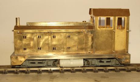
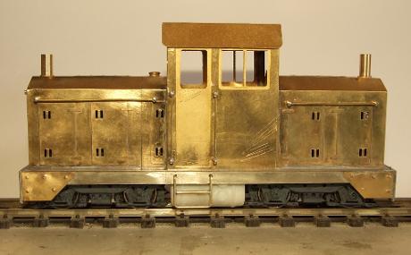
Diesel fuel tanks
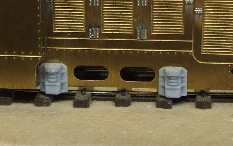
Not very easy to photograph, these are dummy tank sides to cover the cast chassis center piece on a Bachmann chassis used under A1 body kits. There are 2 types 25mm long and 10mm diameter, either 4 or 6mm thick. The top picture shows the 4mm ones fitted in place. The top detail is a filler cap and the middle one a fuel gauge. I also made a pair with the details 5mm off center as fitted in the bottom picture as the detail clashed with the cab steps on a center cab loco.
A pair of any type - £2.00
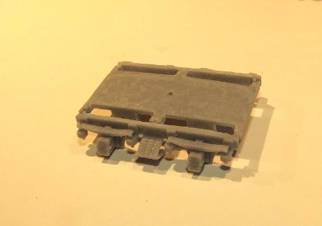
Tralee & Dingle coach bogies
Designed to use the Slaters 21mm gauge CDR wheel sets. They are made in 5 parts, a top, 2 axle retainers and 2 outside frames which assemble with super glue. The ones shown were printed in a new resin that gives a sort of scrappy appearance and remains too flexible after printing. I have since switched to my regular resin which is much better but hard to photograph. I will replace the pictures when I have new bogies and can prime them.
1 pair of T&D bogies - £16.00
I can modify the drawing for 16.5 or 14mm if anyone wants them at the same price.
Left is a picture of modified parts made for a German guy in 16.5mm gauge. The bogies above suit 22L which are 4ft wheelbase, he also wanted bogies for 21L which are slightly different and 3ft 6in wheelbase. These are now available in any gauge and use 14mm wheels, either disc type or Gibson 8 spoke, the bogie price is as above.
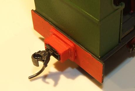
Kadee coupling extenders
For use when there is not enough room to get a Kadee box behind the buffer beam, these extend the coupling outwards by 5mm, less if you file them back a bit. Also of use with my Chopper couplings.
1 pair of extenders - £1.00
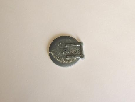
19 mm smokebox door
Made by request for a customer as there was nothing available. I can supply this in different sizes by scaling the drawing if you need a different size.
Smokebox door - £1.50
Locosnstuff is owned by Mark Clark of 12 Adelaide Road, Gillingham, Kent, ME7 4NJ, UK
You can contact me at borsig1958@gmail.com anytime or on 01634 575081 before 8pm
Make a free website with Yola